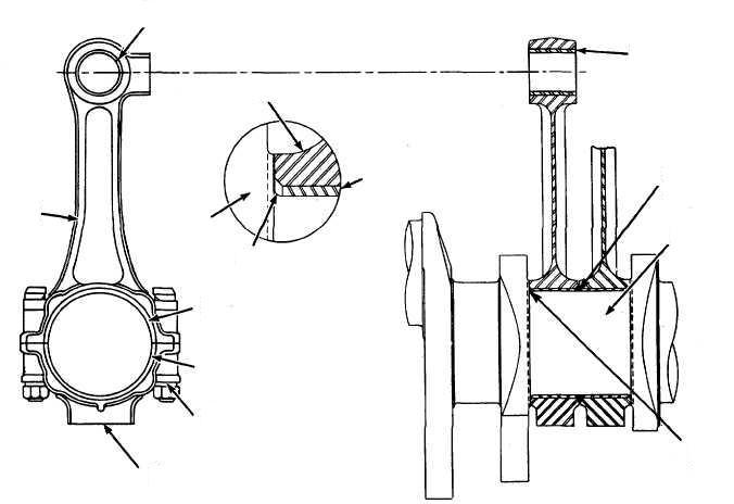
The lower and the upper connecting rod bearing are separated from the connecting rod. They are bolted on to it with tension bolts. The top flange of the connecting rod carries the two upper connecting rod bearing-halves. (Also known as crosshead or top end bearing).
The bottom part of the crosshead bearings are equipped with bearing shells. The two respective bearing covers are lined with white metal. Two screws each locate the bearing shells in the bearing body. As no shims are fitted between bearing lower part and bearing cover the bearing clearance can be adjusted with shims.
The connecting rod bolts for the upper and lower connecting rod bolts are secured by toothed discs. The connecting rod bolts are prestressed by two hydraulic pre-stressing respectively tightening the connecting rod bolts please refer to group.330 in the “maintenance manual”.
The compression shims which are used on the test bed to adjust the compression pressure are fitted between the connecting rod and the upper port of the lower connecting rod bearing. As a rule the shim consists of one part and is stamped with the cylinder number of the respective connecting rod. An exchange of the shims must be avoided by all means.
RN68M 1,7 mm
RN76M 2 mm
RN90M 2 mm
If a thicker shim is to be fitted, it is absolutely essential that the wear ridge in the cylinder liner upper part is removed.
After each change of the shim thickness the clearance between the cylinder cover and the piston is to be checked by making a lead impression in T.D.C (minimum admissible clearance = 5 mm).
The bearing clearance and the functioning of the bearing lubrication are to be checked periodically.
The upper connecting rod bearing, guide shoes and the lower connecting rod bearing are lubricated from the crosshead-oil system. The oil is supplied through the hollow linkage arm into the crosshead pin and further through a longitudinal bore in the connecting rod down to the lower connecting rod bearing. Information regarding the fitted and removing of connecting rods, bearing inspections etc. are found in the “Maintenance manual” under group 330.
The bearing shell in the bearing lower part protrudes on the bearing body butting faces when in unstressed condition. This so called “protraction” is desired by the design. No corrections are to be carried out on bearing shell butting faces nor on the bearing lower part:
Index to sketch below in figure 1
- Bearing cover to upper connecting rod bearing
- Bearing shell to upper connecting rod bearing
- Bearing lower part
- Fixing bolt
- Locking screw
- Connecting rod bolt
- Centring ring
- Connecting rod
- Fixing bolt
- Compression shim
- Upper part of lower connecting rod bearing
- Shims for adjusting vertical bearing clearance
- Bottom part of lower connecting rod bearing
- Fixing screw for bearing shell
- Locking sleeve
- Nut to connecting rod bolt

The crosshead consists of two main parts, the crosshead pin and the guide shoes. The running surfaces of the guide shoes as well as its bores are lined with white metal.
The crosshead pin has a flat, square portion on the middle, which is provided with a bore to receive the piston rod. On either side of this middle portion the journal pins for the upper connecting rod bearings are arranged. The outer cylindrical pins with a smaller diameter are for the guide shoe bearings.
If the bearing pins of the upper connecting rod bearing are slightly damaged on the lower contact surfaces, the crosshead pin can then be turned so that the undamaged upper pin surfaces will be in contact with the lower bearing half.
The oil for lubricating the upper connecting rod bearing is supplied by the crosshead oil system. From the crosshead pin, bores lead to the guide shoes which are connected to the same oil system.
The guide shoes are held in position in longitudinal direction by the end covers which are bolted to the respective front side of crossheads. During operation the guide shoes adjust themselves automatically since there is a certain amount of play between the end covers and the guide shoes. The tongue on the end covers prevent the crosshead pin from turning around its own axis relative to the shoes.
On the top flat of the crosshead is a cylindrical pin which positions the piston rod once they are assembled.

Index to sketch in figure 2 above
- Locking sleeves
- Connecting rod bolt
- Locking screw
- Guide shoe
- Crosshead pin
- Piston rod
- Bearing cover to upper connecting rod bearing
- Bearing shell
- Bearing lower part of the upper connecting rod bearing
- Connecting rod
- Piston rod nut
- Fixing bolt
- Centring ring
- Guide bar
- Guide rail
- Cylindrical pin for positioning the piston rod
- End cover
- Locking plate to the locking arrangement of the locking sleeve


