Let us discuss about a two stroke diesel engine with exhaust gas driven turbocharging and loop scavenge system under two conditions, namely running on increased load and running on part load one by one.
Running on increased load
First stroke: (Expansion stroke)
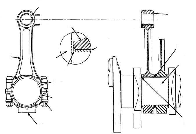
Figure 1: Piston (K) is in top dead centre (TDC). The scavenge ports (S) and exhaust ports (A) are covered by the lower part of the piston. Fuel is injection into the combustion chamb: combustion takes place.

Figure 2: Piston (K) moves downwards under the pressure of the combustion gases, so operating the crank shaft: Expansion. The air present in the buffer space (P) is compressed. The spaces (P) and (H) are subdivided for each cylinder, whereas the space (C) is common for the engine. The valves (E) are closed and a part of the compressed air flows through the valves (D) into the space (H).

Figure 3: The top edge (O) of the piston uncovers the exhaust ports (A). The scavenge ports (S) are still covered: Pre-exhaust. The exhaust gases flow into the exhaust manifold (F). During the further downward movement of the piston, its top edge uncovers the scavenge ports (S). The scavenge ports (S). The scavenging of the cylinders commences. The compressed air in the spaces (H) and (P) flows through the scavenging ports (S) into the cylinder (Z).

Second stroke: (Compression stroke)
Figure 4: Piston (K) is in bottom dead centre (BDC). Scavenging air flows from the space (G) through the valves (E) into the space (P) and through the valves (D) and (B) into the space (H) and finally form the letter through the scavenge ports (S) into cylinder (Z). The remaining exhaust ports (A) via the exhaust manifold (F) to the exhaust turbocharging (T).

Figure 5: Piston (K) moves upwards. The top edge (O) of the piston covers the scavenge ports (S). Scavenging is terminated. The pressure in the exhaust manifold (F) prevents escaping of the air cylinder (Z) through the still open exhaust ports (A). The pressure in the space (P) drops, during the upward movement of the piston, below the constant pressure in the space (G). The valves (E) remain open and the valves (D) and (B) close.

Figure 6: Compression in cylinder (Z) set up by the upwards stroke of piston (K). The turbocharger (L), operated by the exhaust gases, supplies compressed air in an uninterrupted flow through the cooler (R), space (G) and the open valves (E) into the space (P). The charge air is compressed in cylinder (Z) so that its temperature rises well above the ignition temperature of the fuel used. The fuel is injected into the combustion space shortly before the compression stroke is terminated. The fuel then ignites without any extraneous ignition aid.

Part load
For operation in the part load range an auxiliary blower (V) driven by an electric motor (M) is switched on. This blower sucks air from space (G) and delivers it into space (I). The peak pressure in the space (H) set up by the downward moving of piston (K), is higher than the pressure in space (I).
There by, the valves (B) prevent air flowing back form space (H) into space (I). As soon as (with increased load) the pressure in space (G) is sufficient for normal operation, the blower is automatically switched off.
The steps involved during part load of the engine are as follows:
Piston (K) in TDC. The scavenging ports (S) and the exhaust ports (A) are closed by the piston underside. Fuel is injected into the combustion space: combustion.
The top edge (O) of piston uncovers the exhaust ports (A): pre-exhaust. During the further downward movement of the piston, the top edge of the piston also uncovers the scavenging ports (S). The scavenging commences. The compressed air from the spaces (H) and (P) flows through the scavenging ports (S) into the cylinder (Z). The valves (D) are open.
Piston after BDC. Second part of scavenging. The air supplied from the auxiliary blower (V) flows via the space (I) through the open valves (B) into the space (H) and from there through the scavenging ports (S) into the cylinder (Z) until finally the piston covers the scavenging ports. The air delivered from the turbocharging (T) is flowing through the valves (E) into the buffer space (P).
The upward moving piston (K) compresses the air in the cylinder (Z). The valves (B) are closed.
Two Stroke Diesel Engine Mechanism,