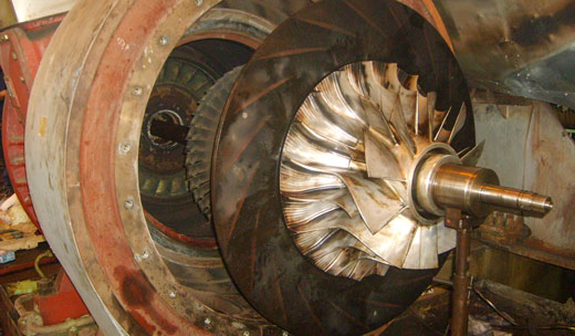
The air required by the engine for combustion purposes is supplied by one or more turbochargers, which are located above the exhaust collection line.
To prevent foreign particles from the turbochargers, protection grids are provided in the exhaust pipes underneath the gas-inlet housing. Expansion pieces are fitted between the gas-inlet housing and the exhaust pipes from being transmitted to the turbochargers.
Information concerning the description, maintenance and cleaning of the turbochargers during operation etc. may be obtained from the service manual issued by the turbocharger manufacturer.
When the engine is in the standstill condition, the rotor of the turbocharger is turned as soon as the auxiliary blower is started up. Whereas this does not give rise to any danger in the case of turbochargers with self-lubrication, units with external lubrication sources may suffer damage to the bearings, as is the case when oil pressure is non-existant or too low.
For such cases, the pressostat in the switch box for the auxiliary blower must be connected up and set to provide for the minimal oil pressure needed for the turbocharger.
(For BBC turbochargers 0.5 bar, and according to the valves specified in the turbocharger manuals for other makes).
In other words, it is the duty of the pressostat, to prevent the switching-on of the auxiliary blower if lubrication of the turbocharger bearings in not assured.
The engine is equipped with an auxiliary blower which is driven by an electric motor. It supplies additional air into the cylinders in order to improve the combustion of partial load of the engine. The auxiliary blower can, depending on the position of the switch on the switch box, be manually or pneumatically controlled.
When an automatic control the auxiliary blower is put into operation as soon as the fuel control linkage is moved away from “0” position. Through this a switch is actuated by a cam fitted on the intermediate control shaft of the fuel control linkage. On reaching a certain scavenge air pressure, the auxiliary blower is switched off by a pressostat. A time relay prevents the auxiliary blower from being stopped immediately when the fuel control linkage is moved to “0” position for a short time. (e.g. during maneuvering).
In the case of installations, in which the turbocharger is supplied with oil from an external source, it is the duty of the pressostat, to ensure that the auxiliary blower cannot be switched on before the minimal oil pressure is available. Since the auxiliary blower causes the rotor of the turbocharger to turn over, the absence of lubricating oil would result in damage to the bearings..
The minimal oil pressure for BBC turbochargers is 0.5 bar. Please observe the instructions given by the manufacturer for the other turbocharger types.
We advice, the opening of the drain cock located at the lowest point of the housing, each time before into operation or once a day during operation because of possible collected condensation water.

Index to sketch
- Electric motor
- Labyrinth bush
- Cover
- Blower wheel
- Sheet metal joint ring
- Housing
- Cover
- Blower wheel up
- Drain cock
- Switch box
- Switch (hand and automatic)
The air supplied by each turbochargers flow through an air cooler into the scavenge air receiver. The task of the air cooler is to cool down the heated up compressed scavenge air before it enters the scavenge air receiver respectively the cylinders.
The cooling water passes through the cooling tubes of the cooler stack can expand length wish to one side. The cooler stack can as a complete unit be removed from the.
Service instructions
The air coolers must during operation be continuously vented, as insufficiently vented coolers cause operational difficulties due to accumulation of air. (High scavenge air temperature in turn causes increased exhaust temperature).
The scavenge air temperature must during operation be regularly checked.
When running the engine at part load, as well as during manoeuvring, the amount of cooling water passing through the air cooler must be regulated so that the scavenge air temperature after the coolers does not drop not drop too low, otherwise condensation will from and the danger of corrosion will increase. The cooing water outlet temperature of the cooler is to be observed.
The difference between the cooling water inlet temperature of the cooler and the scavenge air temperature after the air coolers can be used as an approximate yardstick for the efficiency of the air coolers. These two temperatures are to be checked on all air coolers at regular intervals. If this temperatures difference increase markedly with the engine load remaining unchanged and the cooling water temperature and quantity are constant, this points to advanced fouling of the air cooler concerned.
With fouled air coolers (air side) the pressure losses across increases. The measured pressure drop is however no exact yardstick for the degree of the cooler fouling, as the pressure loss varies with the quantity of air.
Signs of cooler fouling
Fouling of the cooler on water side is indicated by a decrease of temperature difference between cooling water inlet and outlet.
Fouling of the cooler on air side is indicated by an increase of pressure drop of the scavenge air across the air cooler. The air temperature difference between inlet and outlet decreases.
Cleaning the air coolers
The air coolers can be cleaned on air and water sides to a certain points without removing cooler stack. For cleaning heavily fouled or to repair leaking cooler stacks, they have to be withdrawn with the help of a device which is in the tool set.


Index to sketches
- Cover with in-and outlet connections
- Joint
- Rubber “0” ring
- Bolt
- Flange
- Cooler housing
- Side wall
- Guide screw
- Cooler tubes
- Tube and plate joint
- Guide cover
- Control cover
- Scavenge air channel before cooler
- Scavenge air channel after cooler
- Thermometer connection
- Drain connection
A Cooling water outlet
D Connection for cleaning chemically
E Cooling water inlet
G Discharge
L Venting
Turbocharger Construction & Maintenance,