Marine radar is an instrument of perfect synchronization. It contains no calculator or computer to do its basic function. Range and bearing are obtained by the fact that each component does a specific job at the correct time.
Radar Units
Marine radar consists mainly of four units – the transmitter, the aerial or scanner, the receiver and the display unit. The transmitter sends out short powerful bursts of electro-magnetic energy, called pulses, through the scanner at a specific number of times per second, called the pulse repetition frequency (PRF) or pulse recurrence rate (PRR). These pulse travels at the speed of light
(300 meters per micro-second*[1] or 6.173 micro-seconds per nautical mile) and when they strike any object (target) in their path, they are reflected back to the scanner as echoes. The receiver processes each echo and causes it to show up visually as a bright spot, on the screen of the display unit.

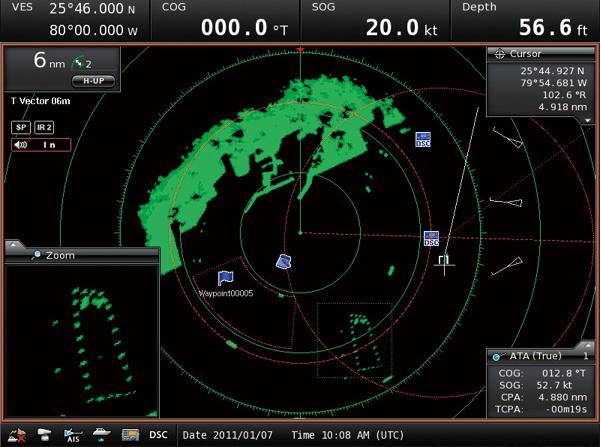
The display unit has a circular screen representing on a scale, an actual area around the ship is called the plan position indicator (PPI) because it gives a bird’s eye view (or plan) of the positions of targets. The distance represented by the radius of the screen is called the range scale and this can be varied, by a switch, as desired by the observer.
The underside of the screen is coated with a phosphor compound which glows when struck by electrons and then fades off slowly. This slow fading off, of the spots on the screen, is called the persistence or after-glow of the screen and helps the observer to view the screen properly at leisure.
A thin stream of electrons is made to strike the underside of the screen and move radially across from the centre to the edge of the screen, at a number of times per second equal to the PRE, thereby creating one radial line (called the trace) on the screen for every pulse sent out by the scanner. When an echo is received and processed by the receiver, a sudden brightening and fattening of the tracing spot occurs momentarily. Though the tracing spot is moving continuously during this time, the blip created by it (referred to as paint) remains stationary and visible due to the persistence of the screen. This is how radar detects the presence of a target in the vicinity.
Range determination
As explained earlier, there is one trace created for every pulse transmitted. The tracing spot leaves the centre, on its radial path, at the same instant that the pulse leaves the scanner. The tracing spot is made to move at a scale speed equal to half that of radio waves (i.e. at a scale speed of 150 metres per microsecond), so that in the time taken for radio waves to travel 2 miles, the tracing spot would travelled a scale distance of 1mile on the screen.
If a target was situated at a range of 3 miles, the pulse would travel 3 miles to the target and the echo would travel 3 miles back, a total distance of 6 miles. During this time, the tracing spot would have travelled a scale distance of 3 miles, from the centre of the PPI. That is to say, since the radius of the screen represents a definite distance, the distance of the paint from the centre of the screen, using the same ratio, gives the range of the object.
In order to accurately obtain the range of a target, as described above, two methods are provided on the display unit:-
(1) Range rings: A series of concentric, equidistant circles, called range rings or calibration rings, are made to appear, centred over the PPI. Each range ring represents a definite value of range and hence the range of a target can be visually estimated with reasonable accuracy, even if a range ring does not exactly pass through the paint of the target on the screen.
(2) Variable range marker: A circle with a variable radius is provided, the radius being controlled by a rotary knob. The value of the radius in miles and decimal of a mile is indicated by a digital display. The radius of the circle is adjusted until its circumference passes through the nearest edge of the paint of a target on the screen and the range is read off the digital display.
Bearing determination
The energy sent out by the scanner is made unidirectional (it is beamed in one direction at a time). The scanner is made to rotate clockwise (when viewed from above) at a very constant speed (between 12 & 30 RPM). The trace on the screen is also made to rotate and is synchronized with the scanner such that when the scanner point’s right ahead, the trace is at the 12 O’clock position of the PPT and when the scanner points to the starboard beam, the trace is at the 3 O’clock position, and so on.
The PRF is so high (500 to 4000) compared to the Rpm (12 to 30) that the angle rotated by scanner, between the transmission of a pulse and the arrival of the echo from a far off target (i.e., the time taken for the tracing spot top go from the centre to the edge of the screen), is negligible.
So the paint of a target would appear in such a position on the PPT that the relative bearing of the target is the angle at the cnetre, measured clockwise from the 12 O’clock position of the PPT, to the paint. This can be read off using a concentric,, circular scale fixed around the PPT, graduated from 00 to 3590 in a clockwise direction, with its 00 at the 12 O’clock position of the PPT.
A stationary radial line, called the heading marker, extending from the centre of the PPT to the zero of the bearing scale, is constantly visible for reference. To facilitate reading off, of the relative bearing, two methods are provided on the display unit:-
1) Mechanical cursor: A separate circular plastic sheet, called the mechanical cursor, is fitted, centred over the PPT. It has a diametrical line etched on it. The cursor is rotated unit this line passes through the target on the screen, and the reading where it passes over the graduated scale is the relative bearing. When the display is gyro-stabilized, the bearing will be true.
2) Electronic bearing line: A radial line (which may be dotted or continuous) is made to appear on the screen, when desired. This line can be rotated about the centre of the screen by a control knob. The angle rotated by the line, in a clockwise direction from the heading marker, is indicated by a digital display. The line is rotated until it passes through the blip on the screen and the relative bearing read off, from the digital display. When the display is gyro-stabilized, the bearing will be true.
Note: [1] 10 6 micro-seconds = 1 second, 1.852 kilometers = 1 nautical mile, 1 kilometer = 0.54 nautical mile.
We will continue with this discussion in our next article in which we will take a look at important radar characteristics.
How Does Marine Radar Work?,